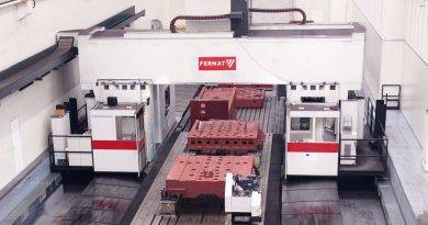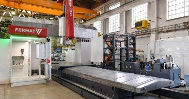
CNC Gantry machining centers series FRF, FRU, FRP
working dimensions from 3000 x 2900 x 1250 mm up to 22000 x 6500 x 2000 mm
TOS FRF
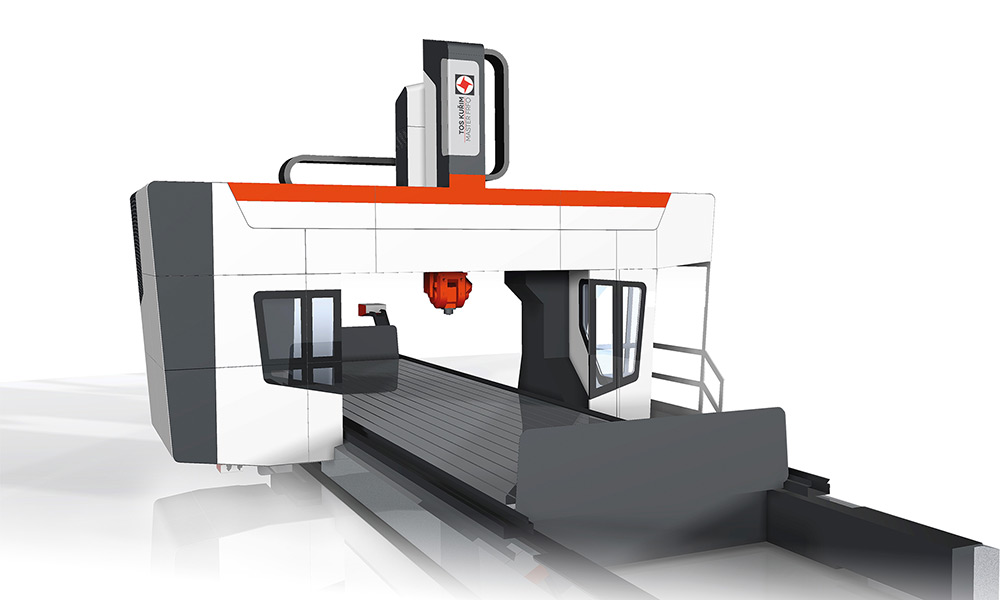
This machining centre with FRF movable gantry can be found in more than 20 countries. Customers prefer this machine mainly because of its robust structure, high throughput in a small installation area and high performance. Its high productivity has been demonstrated with more than 120 customers.
The FRF machining centres boast a wide range of applications. They enable machining of complex workpieces of large dimensions. For example: machining of aircraft engines, bogies for locomotives and subway rolling stock, Kaplan turbines, parts of cranes, turbine casings, etc.
Technical data FRF
| Type | Unit | FRF 200 | FRF 250 | FRF 300 | FRF 400 |
| Working travel | |||||
| X (longitudinal axis) | [mm] | 4000 / 5000 / 6000 / 7000 / 8000 / 10000 / 12000 / 14000 / 16000 / 18000 / 20000 / 22000 / 24000 | 4000 / 5000 / 6000 / 7000 / 8000 / 10000 / 12000 / 14000 / 16000 / 18000 / 20000 / 22000 / 24000 | 4000 / 5000 / 6000 / 7000 / 8000 / 10000 / 12000 / 14000 / 16000 / 18000 / 20000 / 22000 / 24000 | 4000 / 5000 / 6000 / 7000 / 8000 / 10000 / 12000 / 14000 / 16000 / 18000 / 20000 / 22000 / 24000 |
| Y (cross axis) | [mm] | 2900 | 3400 | 3900 | 4900 |
| Z (vertical axis) | [mm] | 1500 | 1500 | 1500 | 1500 |
| Table width | |||||
| Width | [mm] | 2 000 | 2 500 | 3 000 | 4 000 |
| Feed range | |||||
| X | [mm/min] | 1 – 20000 (1 – 30000) | 1 – 20000 (1 – 30000) | 1 – 20000 (1 – 30000) | 1 – 20000 (1 – 30000) |
| Y | [mm/min] | 1 – 20000 (1 – 30000) | 1 – 20000 (1 – 30000) | 1 – 20000 (1 – 30000) | 1 – 20000 (1 – 30000) |
| Z | [mm/min] | 1 – 20000 (1 – 30000) | 1 – 20000 (1 – 30000) | 1 – 20000 (1 – 30000) | 1 – 20000 (1 – 30000) |
| Clearance between columns | |||||
| Clearance | [mm] | 2550 | 3050 | 3550 | 4550 |
| Clearance between table and cross–rail | |||||
| Clearance | [mm] | 2050 | 2050 | 2050 | 2050 |
| Motor output | |||||
| Output | [kW] | 30 / 37 / 45 | 30 / 37 / 45 | 30 / 37 / 45 | 30 / 37 / 45 |
TOS FRU
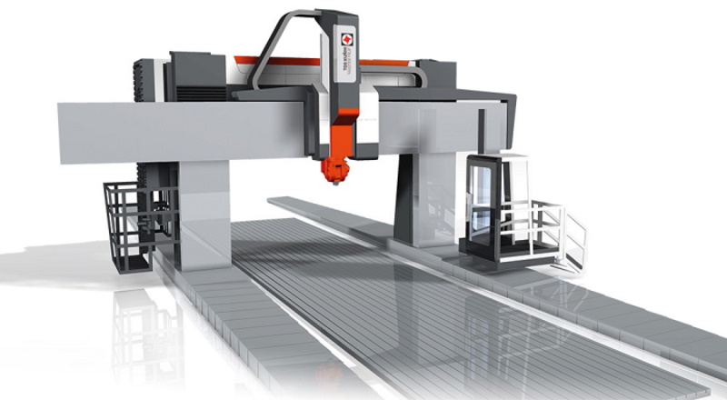
A basic feature of the FRU machining centre is the travel gantry that allows full utilisation of the work space. It is designed for machining complex workpieces. Its flexibility mainly results from the possibility of using versatile spindle heads produced by TOS Kuřim.
The high productivity of the machine is the result of its structural design. Thanks to large material removal, solid structure and automatic exchange of spindle heads, TOS FRU can be used for the most demanding operations. Customers use the machine for machining tram switches, steam turbines, ship engines, blades of Kaplan turbines, aircraft parts, etc.
Technical data FRU
| Type | Unit | FRU 200-500 | FRU 300-800 |
| Working travel | |||
| X (longitudinal axis) | [mm] | 4000 – 22000 | 4000 – 24000 |
| Y (cross axis) | [mm] | 3500 – 6500 | 5750 – 10750 |
| Z (vertical axis) | [mm] | 1500 / 2000 | 1500 / 2000 |
| W (movable cross–rail, optional) | [mm] | 2000 / 2500 | 2250 / 2800 / 3800 |
| Feed range | |||
| X | [mm/min] | 1 – 20000 (1 – 30000) | 1 – 15000 |
| Y | [mm/min] | 1 – 20000 (1 – 30000) | 1 – 20000 |
| Z | [mm/min] | 1 – 15000 (1 – 20000) | 1 – 15000 |
| W (movable cross–rail, optional) | [mm/min] | 1 – 4000 | 1 – 4000 |
| Clearance between columns | |||
| Clearance | [mm] | 3000 – 6000 | 4000 – 9000 |
| Clearance between table and cross–rail | |||
| Clearance | [mm] | 2800 – 3500 | 3500 – 5500 |
| Motor output | |||
| Output | [kW] | 30 / 37 / 45 / 60 | 60 / 71 / 100 / 113 |
TOS FRP
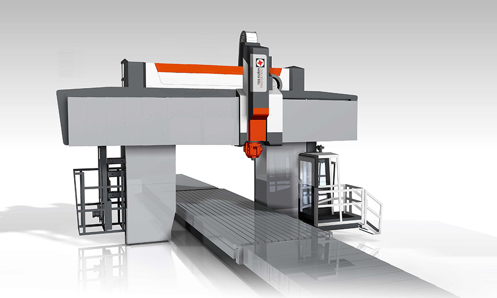
The FRP gantry centre is designed for standard or high-speed machining of large and very complex workpieces. It consists of a bed on which the table is shifted and a fixed gantry with a movable cross-rail. Customers can choose between a linear and hydrostatic guideway.
FRP also allows turning, which is possible thanks to an optional VTL table. The machine is equipped with versatile spindle heads, which allow a variety of machining operations. The customers choose it for machining aircraft engines, locomotive diesel engines or steam turbine casings. Thanks to its high performance and torque, FRP can also be used for roughing operations.
Technical data FRP
| FRP 150-250 | FRP 200-400 | FRP 200-450 | ||
| Working travel | ||||
| X (longitudinal axis) | [mm] | 3000 / 4000 / 5000 | 5500 – 13500 | 5500 – 13500 |
| Y (cross axis) | [mm] | 2900 / 3400 / 3900 | 3300 – 5800 | 3800 – 6800 |
| Z (vertical axis) | [mm] | 1250 / 1500 | 1500 / (2000) | 1500 / 2000 |
| W (movable cross–rail, optional) | [mm] | 2000 | 2250 | |
| Table width | ||||
| Width | [mm] | 1500 / 2000 / 2500 | 2000 – 4000 | 2000 – 4500 |
| Feed range | ||||
| X | [mm/min] | 1 – 15000 (1 – 30000) | 1 – 15000 | 1 – 15000 |
| Y | [mm/min] | 1 – 20000 (1 – 30000) | 1 – 20000 | 1 – 20000 |
| Z | [mm/min] | 1 – 20000 (1 – 30000) | 1 – 20000 | 1 – 15 000 (1 – 20000) |
| W (movable cross–rail, optional) | [mm/min] | 1 – 4000 | 1 – 4000 | |
| Clearance between columns | ||||
| Clearance | [mm] | 2600 / 3100 / 3600 | 3050 – 4550 | 3050 – 5550 |
| Clearance between table and cross rail | ||||
| Clearance | [mm] | 1800 | 1800 – 2500 | 2770 |
| Motor output | ||||
| Output | [kW] | 37 | 30 / 37 / 45 / 60 | 60 / 71 |
For all inquiries and more info about our machines please contact us by:
Phone: +420 541 101 111

